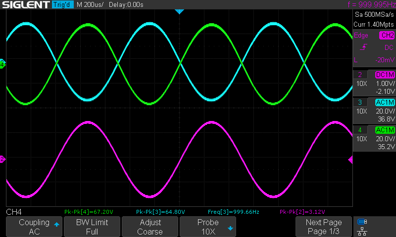
Finished wiring up the phase splitter. For the circuit, I used the ubiquitous long tail pair used in a Marshall Plexi 50 watt. Due to my use of larger coupling caps, it was very fussy to wire up, and I worried about some error causing all sorts of problems or emitting the magic smoke. Imagine my pleasure when I hooked it up to the function generator and captured the voltage it was placing on the grids of the EL34s.
We see the 3.12 volt sine wave coming in and the resulting 64.8/67.2 volts on the EL34 grids, a voltage gain of 21 or 26.5 db. I note the two outputs are very close in voltage.
Phase Splitter with the power tubes
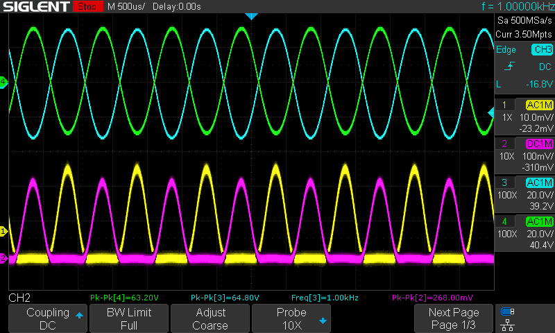
Its days like this that a four channel scope with screen capture is a wonderful thing. We see the power stage operating properly when driven by the phase splitter. The EL34s are not well matched, as evidenced by their different idle currents, but this is good enough for a general smoke test…
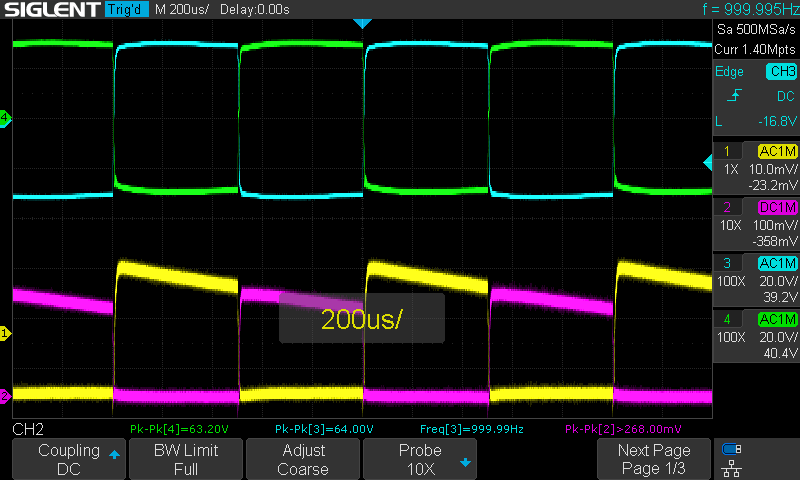
Input Stage Checkout
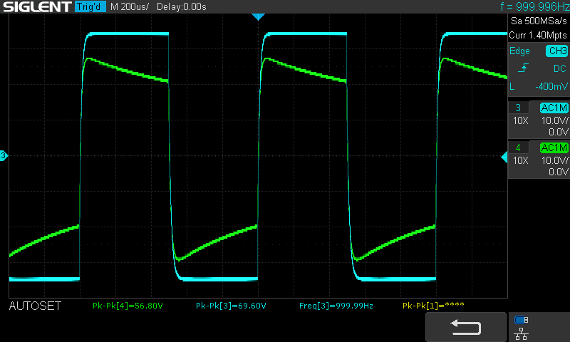
Doing a smoke test on the input triodes. The input signal is a 3 volt square wave–I wanted to see what kind of voltages it could emit and these are delightfully high. The configuration here is the typical Marshall input with a regular and ‘high’ stage. The difference being in the bias resistor and capacitor. The different responses to the square wave are to be expected. Here we are seeing a voltage gain of 18.7 on one and 23 on the other, or 16 and 17.6 db. Since the phase splitter is emitting close to full power driving voltage with a 3 volt input, I will need to look at how I want to structure the gain staging in the amp. I will not have a traditional tone control circuit, so the means of hooking it up to the phase splitter input will require some experimentation. There will be a rheostat for each side of the triode pair, and the relative levels there act to some extent as a tone control. A single input will drive the triodes, acting as the traditional jumper between the regular and high inputs.